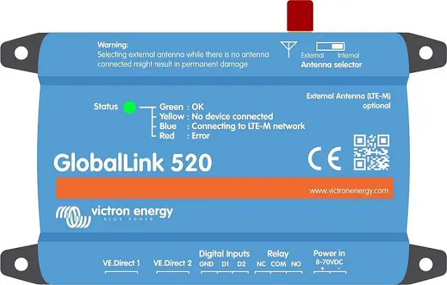
victron energy RemoteGPIO Communication Module

Informace o produktu
Specifikace
- Product Name: RemoteGPIO Communication Module
- Compatibility: Works with Victron’s Venus OS
- Architecture: Core Engine and Communication Modules
- Communication Protocols: MQTT, Modbus, etc.
- Local MQTT Broker: localhost:1883
This document describes the RemoteGPIO driver architecture and explains how to develop a custom communication module to integrate any I/O device with Victron’s Venus OS.
Architektura systému
The RemoteGPIO system is designed in two distinct parts to ensure stability and modularity:
- The Core Engine (dbus-rgpio.py): This is the heart of the system, running as a persistent service. It knows nothing about specific hardware protocols. Its sole responsibilities are:
- Managing the kernel module for virtual GPIOs.
- Creating and managing D-Bus services (com.victronenergy.switch.*).
- Creating the /run/io-ext/ structure for digital input discovery by other Venus OS services.
- Providing a simple internal MQTT API for modules to communicate with it.
- Communication Modules (e.g., dingtian_mqtt_bridge.py): These are independent scripts, each running as its own service. A communication module is responsible for:
- Communicating with a specific piece of hardware (e.g., Dingtian, Waveshare) using its native protocol (MQTT, Modbus, etc.).
- Translating hardware states into API calls for the Core Engine.
- Translating API commands from the Core Engine into hardware commands.
File Structure & Service Management
To integrate a new communication module, you need to follow this structure and configuration.
A. File Místa
- Module Script: Your Python script must be placed in /data/RemoteGPIO/modules/.
- Konfigurace File: Your module’s .ini file must be in /data/RemoteGPIO/conf/.
- Service Directory: Your daemontools service definition must be in /service/. For example, a new module named my_new_bridge would have its service at/service/my_new_bridge.
B. Service Control with setup_rgpio
The setup_rgpio.py module provides a user-friendly way to start and stop communication modules directly from the Venus OS GUI. To make your module controllable, you must add it to /data/RemoteGPIO/conf/setup_rgpio.ini.
Example: To add a new module called my_new_bridge controlled by Relay 4, you would edit setup_rgpio.ini as follows:
Relay4 = My New Module
Service4 = my_new_bridge
- Relay4: This is the friendly name that will appear in the Venus OS GUI for that relay.
- Service4: This is the exact name of your service directory in /service/.
When a user toggles “Relay 4” in the GUI, the setup_rgpio module will execute svc -u /service/my_new_bridge (to start) or svc -d /service/my_new_bridge (to stop).
Internal API Specification
(via MQTT)
All communication with the Core Engine is done via the local MQTT broker at localhost:1883.
A. Device Registration & Un-registration
This is the most important call. It tells the Core Engine that a device exists and how it is configured.
- Topic: rgpio/api/device/register/<SERIAL>
- Payload for Registration: A JSON string describing the device.
- Payload for Un-registration: The string “UNREGISTER”.
Example: Registrace zařízení
To register a new device with serial MYDEVICE_001 that has 4 inputs and 8 relays:
- Topic: rgpio/api/device/register/MYDEVICE_001
- Payload: {“serial”: “MYDEVICE_001”, “num_inputs”: “4”, “num_relays”: “8”, “device_instance”: “260”}
- Retain Flag: Must be True.
Upon receiving this, the Core Engine will:
- Create the D-Bus service com.victronenergy.switch.MYDEVICE_001.
- Create the directory /run/io-ext/MYDEVICE_001 with the appropriate symlinks.
Example: Un-registering a Device
This should be done when your module shuts down gracefully.
- Topic: rgpio/api/device/register/MYDEVICE_001
- Payload: “UNREGISTER”
- Retain Flag: Must be True.
B. Device Status (Connection)
This tells the Core Engine if the communication module is actively connected to the physical hardware. This updates the /State and /Connected paths in the D-Bus service.
- Topic: rgpio/api/device/status/<SERIAL>
- Payload: “CONNECTED” or “DISCONNECTED”.
- Retain Flag: Must be True.
Example: Marking a device as connected
- Topic: rgpio/api/device/status/MYDEVICE_001
- Payload: “CONNECTED”
C. Digital Inputs (Module -> Engine)
This communication is one-way: from your module directly to the Linux kernel’s sysfs. It does not use the MQTT API.
When your module detects a change on a physical input, it must write the new state (0 for OFF, 1 for ON) to the symlink created by the Core Engine.
Example: Updating Input 2
Your module detects that input 2 of MYDEVICE_001 has turned ON.
- The path to write to is /run/io-ext/MYDEVICE_001/input_2.
- The value to write is “1”.
- You must respect the sysfs rules for writing:

D. Relay Commands (Engine -> Module)
This is how the Core Engine tells your module to change the state of a physical relay.
Your module must subscribe to this topic.
- Topic: rgpio/api/relay/set/<SERIAL>/<RELAY_NUMBER> (1-based)
- Payload: “ON” or “OFF”
Example: Command to turn on Relay 4
- Topic: rgpio/api/relay/set/MYDEVICE_001/4
- Payload: “ON”
Your module will receive this message and must translate it into the appropriate command for your hardware.
E. Relay State Feedback (Module -> Engine)
This allows your module to inform the Core Engine of a relay’s actual state, for example, if it was changed manually on the device itself.
- Topic: rgpio/api/device/relay/read/<SERIAL>/<RELAY_NUMBER> (1-based)
- Payload: “ON” or “OFF”
Example: Reporting that Relay 1 is now OFF
- Topic: rgpio/api/device/relay/read/MYDEVICE_001/1
- Payload: “OFF”
The Core Engine will receive this and update the /SwitchableOutput/relay_1/State path in DBus to 0.
F. Setting Relay Names (Optional)
Your module can set the default names of the relays as they appear in the Venus OS GUI.
- Topic: rgpio/api/device/<SERIAL>/Relay_<RELAY_NUMBER> (1-based)
- Payload: The desired name (string).
Example: Naming Relay 1 “Water Pump”
- Topic: rgpio/api/device/MYDEVICE_001/Relay_1
- Payload: “Water Pump”
This will update the /SwitchableOutput/relay_1/Name path in DBus.
Často kladené otázky
How do I add a new communication module?
To add a new communication module, follow the file structure guidelines and configure the module in setup_rgpio.ini.
How can I register a new device with the Core Engine?
How can I register a new device with the Core Engine?
Dokumenty / zdroje
 |
victron energy RemoteGPIO Communication Module [pdfPokyny RemoteGPIO Communication Module, RemoteGPIO, Communication Module, Module |
