1. Úvod
This manual provides essential information for the safe and efficient operation, installation, and maintenance of the ABB ACS150 Micro Series AC Variable Frequency Drive (VFD). The ACS150-03U-04A1-4 is a 2.0 HP, IP20 rated micro drive designed for wall mounting, operating with a 480 VAC three-phase input and providing a 480 VAC output at 4.1 Amps. It is part of the ACS150 series, known for its compact design and reliability in industrial applications.
Please read this manual thoroughly before attempting any installation, operation, or maintenance procedures to ensure proper functionality and to prevent personal injury or equipment damage.
2. Bezpečnostní informace
VAROVÁNÍ: Electrical shock hazard. Only qualified personnel should perform installation, commissioning, and maintenance of this equipment. Disconnect all power before working on the drive.
- Vždy dodržujte místní a národní elektrotechnické předpisy a předpisy.
- Zajistěte správné uzemnění měniče a motoru.
- Nedotýkejte se elektrických součástí, když jsou připojeny k napájení.
- Protect the drive from moisture, dust, and extreme temperatures.
- Při práci s elektrickými systémy používejte vhodné osobní ochranné prostředky (OOP).
3. Konec produktuview a Komponenty
The ABB ACS150 Micro Series VFD is designed for compact installations. Below are images illustrating the drive and its key components and layout.
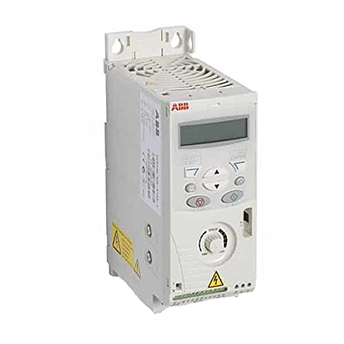
Obrázek 3.1: Přední strana view of the ABB ACS150 Micro Series AC VFD. This image shows the compact design of the drive, including the integrated control panel and cooling fins.

Figure 3.2: Key components of the ABB ACS150 VFD. This diagram highlights important features such as the removable clip for brand labeling, integrated interface, FlashDrop connection, integrated potentiometer, I/O connections, analog input signal selector (U/I), EMC filter grounding screw (EMC), and varistor grounding screw (VAR). It also points to the input, brake resistor, and motor connections.
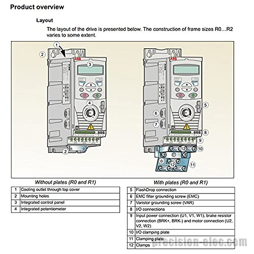
Figure 3.3: Layout of the drive for frame sizes R0 and R1. This image shows two configurations: one without plates and one with plates. Key numbered components include: 1) Cooling outlet through top cover, 2) Mounting holes, 3) Integrated control panel, 4) Integrated potentiometer, 5) FlashDrop connection, 6) EMC filter grounding screw (EMC), 7) Varistor grounding screw (VAR), 8) I/O connections, 9) Input power connection (U1, V1, W1), brake resistor connection (BRK+, BRK-) and motor connection (U2, V2, W2), 10) I/O clamping plate, 11) Clamping plate, and 12) Clamps.
4. Technické specifikace
| Specifikace | Hodnota |
|---|---|
| Číslo modelu | ACS150-03U-04A1-4 (P/N: 68582113) |
| Výkonový jmenovitý | 2.0 HP |
| Vstupní objemtage | 480 VAC Three Phase |
| Výstupní objemtage | 480 VAC |
| Výstupní proud | 4.1 Amps |
| Hodnocení krytí | IP20 (NEMA 1/IP21 when wall mounted) |
| Typ montáže | Držák na zeď |
| Rozměry produktu (D x Š x V) | 8 x 2.8 x 5.6 palce |
| Hmotnost položky | 2.9 libry |
| Výrobce | OBR |
| Datum první dostupnosti | 6. března 2015 |
5. Instalace a nastavení
5.1 Montáž
The ACS150 drive is designed for wall mounting. Ensure the mounting surface is stable and capable of supporting the drive's weight. Allow adequate clearance for ventilation around the drive, especially above the cooling outlet (refer to Figure 3.3, item 1).
5.2 Elektrické připojení
All electrical connections must be performed by a qualified electrician in accordance with all applicable electrical codes. Ensure power is disconnected before making any connections.
5.2.1 Připojení napájení
Connect the three-phase 480 VAC input power to terminals L1, L2, and L3. Connect the motor to terminals U2, V2, and W2. Ensure proper grounding of the drive and motor frame. Refer to the diagram below for an overview of power connections.

Figure 5.1: Power connections and control interfaces. This diagram illustrates the wiring for the 3-phase power supply (L1, L2, L3), input choke, EMC filter, brake chopper, brake resistor, and AC motor (U2, V2, W2). It also shows the control interface connections including programmable digital inputs (DI1-DI5), analog input (AI), relay output, and various grounding points.
5.2.2 Control Connections (I/O Terminals)
The drive features various I/O terminals for control signals. The default connection of control signals depends on the application macro selected. Refer to the diagram below for the I/O terminal layout.
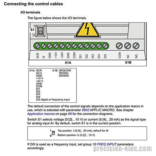
Figure 5.2: I/O terminals (X1A and X1B). This diagram details the pinout for analog input (AI), ground (GND), +10V, +24V, common (COM), and digital inputs (DI1-DI5) on X1A. X1B shows relay output connections (COM, NC, NO). It also indicates the S1 switch for selecting analog input signal type (current or voltagE).
The S1 switch selects the voltage (0 [2]...10 V) or current (0 [4]...20 mA) as the signal type for analog input AI. By default, switch S1 is in the current position. If DI5 is used as a frequency input, set group 18 FREQ INPUT parameters accordingly.
6. Návod k obsluze
The ACS150 VFD can be operated via its integrated control panel or external control signals connected to the I/O terminals. The integrated control panel allows for setting parameters, monitoring drive status, and manual control.
6.1 Obsluha ovládacího panelu
- Start/Stop: Use the dedicated buttons on the control panel to start and stop the motor.
- Ovládání rychlosti: Adjust the integrated potentiometer (refer to Figure 3.2) to change the motor speed.
- Nastavení parametrů: Navigate through menus using the arrow keys and enter/exit buttons to adjust drive parameters such as acceleration/deceleration times, motor data, and I/O configurations.
- Sledování: The display shows real-time operational data like motor speed, current, voltage a chybové kódy.
6.2 Externí ovládání
The drive can be controlled remotely using digital inputs for start/stop commands, analog inputs for speed reference, and relay outputs for status indication. Refer to the wiring diagrams in Section 5.2 for proper connections and the drive's programming manual for parameter configuration.
7. Údržba
Regular maintenance ensures the longevity and reliable operation of the ACS150 VFD. Always disconnect power before performing any maintenance.
- Čištění: Periodically clean the cooling fins and fan to ensure proper airflow and prevent overheating. Use compressed air to remove dust and debris.
- Spojení: Check all electrical connections for tightness and signs of corrosion. Retighten if necessary.
- Kontrola prostředí: Zajistěte, aby provozní prostředí zůstalo v rámci stanovených limitů teploty a vlhkosti.
- Výměna ventilátoru: The cooling fan has a limited lifespan. Replace it if it becomes noisy or stops functioning. Refer to the drive's service manual for fan replacement procedures.
8. Řešení problémů
This section provides general troubleshooting tips for common issues. For detailed fault codes and remedies, refer to the comprehensive ABB ACS150 user manual.
| Problém | Možná příčina | Řešení |
|---|---|---|
| Disk se nezapne | Žádné vstupní napájení; Spálená pojistka; Vnitřní závada | Check power supply; Inspect fuses; Contact ABB support if internal fault suspected. |
| Motor neběží | Incorrect wiring; Parameter settings; Fault trip | Verify motor and control wiring; Check drive parameters (e.g., start command, speed reference); Clear fault and investigate cause. |
| Porucha nadproudu | Přetížení motoru; Zkrat; Rychlá akcelerace | Snižte zátěž; Zkontrolujte motor a kabely, zda nedošlo ke zkratu; Prodlužte dobu rozběhu. |
| Přepětítage chyba | Vysoký vstupní objemtage; Rychlé zpomalení; Rekuperační zátěž | Zkontrolujte vstupní objtage; Increase deceleration time; Consider adding a braking resistor if regenerative load is present. |
| Porucha přehřátí | Blocked ventilation; High ambient temperature; Fan failure | Clear obstructions; Ensure adequate cooling; Check and replace fan if necessary. |
9. Záruka a podpora
Specific warranty terms and conditions for the ABB ACS150-03U-04A1-4 are not provided within this manual. Please refer to the original purchase documentation or contact ABB customer support for detailed warranty information.
For technical support, service, or spare parts, please contact your local ABB representative or visit the official ABB website. Ensure you have the product model number (ACS150-03U-04A1-4) and serial number ready when contacting support.
ABB Official Webmísto: www.abb.com


