
1. Úvod
This manual provides detailed instructions for the DAOKAI NE555 Pulse Frequency Duty Cycle Adjustable Module. This module is designed to generate adjustable square wave signals, making it suitable for various electronic applications, including experimental development, driving stepper motors, and controlling related circuits.
Konec produktuview
The NE555 Pulse Frequency Duty Cycle Adjustable Module is a versatile signal generator based on the NE555 timer IC. It allows users to adjust both the frequency and duty cycle of the output square wave. The module features an LED indicator for output status and offers four selectable frequency ranges for continuous adjustment.
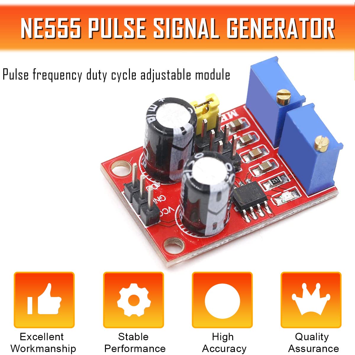
Image 1.1: NE555 Pulse Signal Generator Module. This image highlights the module's key attributes: Excellent Workmanship, Stable Performance, High Accuracy, and Quality Assurance.
Klíčové vlastnosti
- Nastavitelný výstup: Allows adjustment of both pulse frequency and duty cycle.
- Wide Voltage Rozsah: Operates from 5V to 15V DC input.
- Multiple Frequency Ranges: Four selectable ranges for precise frequency control (1Hz-50Hz, 50Hz-1kHz, 1kHz-10kHz, 10kHz-200kHz).
- Visual Output Indicator: An onboard LED indicates the output status.
- Kompaktní design: Small form factor for easy integration into projects.
2. Bezpečnostní informace
Před použitím modulu si prosím přečtěte a pochopte následující bezpečnostní opatření:
- Zajistěte vstupní objtage is within the specified range (5V-15V DC) to prevent damage to the module.
- Observe proper polarity when connecting power to the VCC and GND terminals. Incorrect polarity can damage the module.
- Avoid touching the circuit board components while the module is powered to prevent electric shock or damage from static discharge.
- Nevystavujte modul vlhkosti, extrémním teplotám ani korozivnímu prostředí.
- If you are unsure about any connection or operation, consult a qualified electronics professional.
3. Obsah balení
Ověřte, zda jsou v balení přítomny všechny položky:
- 5 x NE555 Pulse Frequency Duty Cycle Adjustable Module
- 1 x 15-pin Female to Male Dupont Cable
4. Specifikace produktu
Detailed technical specifications for the NE555 Pulse Frequency Duty Cycle Adjustable Module:

Image 4.1: Product Parameters. This image details the input voltage, výstupní proud, výstup amplitude, and input current specifications.
| Parametr | Hodnota |
|---|---|
| Hlavní čip | NE555 |
| Vstupní objemtage | 5V - 15V stejnosměrného proudu |
| Vstupní proud | ≥ 100 mA |
| Output Current (5V supply) | ~15mA (when V-PP > 50%) |
| Output Current (12V supply) | ~35mA (when V-PP > 50%) |
| Výstup Amplituda | 4.2V V-PP (5V input) to 11.4V V-PP (12V input) |
| Nízkofrekvenční rozsah | 1Hz ~ 50Hz |
| Intermediate Frequency Range | 50Hz ~ 1kHz |
| Medium-High Frequency Range | 1kHz ~ 10kHz |
| High Frequency Range | 10kHz ~ 200kHz |

Image 4.2: Module Dimensions. The module measures approximately 32mm (1.26in) in width and 23mm (0.91in) in length.
5. Nastavení a zapojení
Proper connection of the module is essential for its functionality. Refer to the wiring diagram below for guidance.
Schéma zapojení
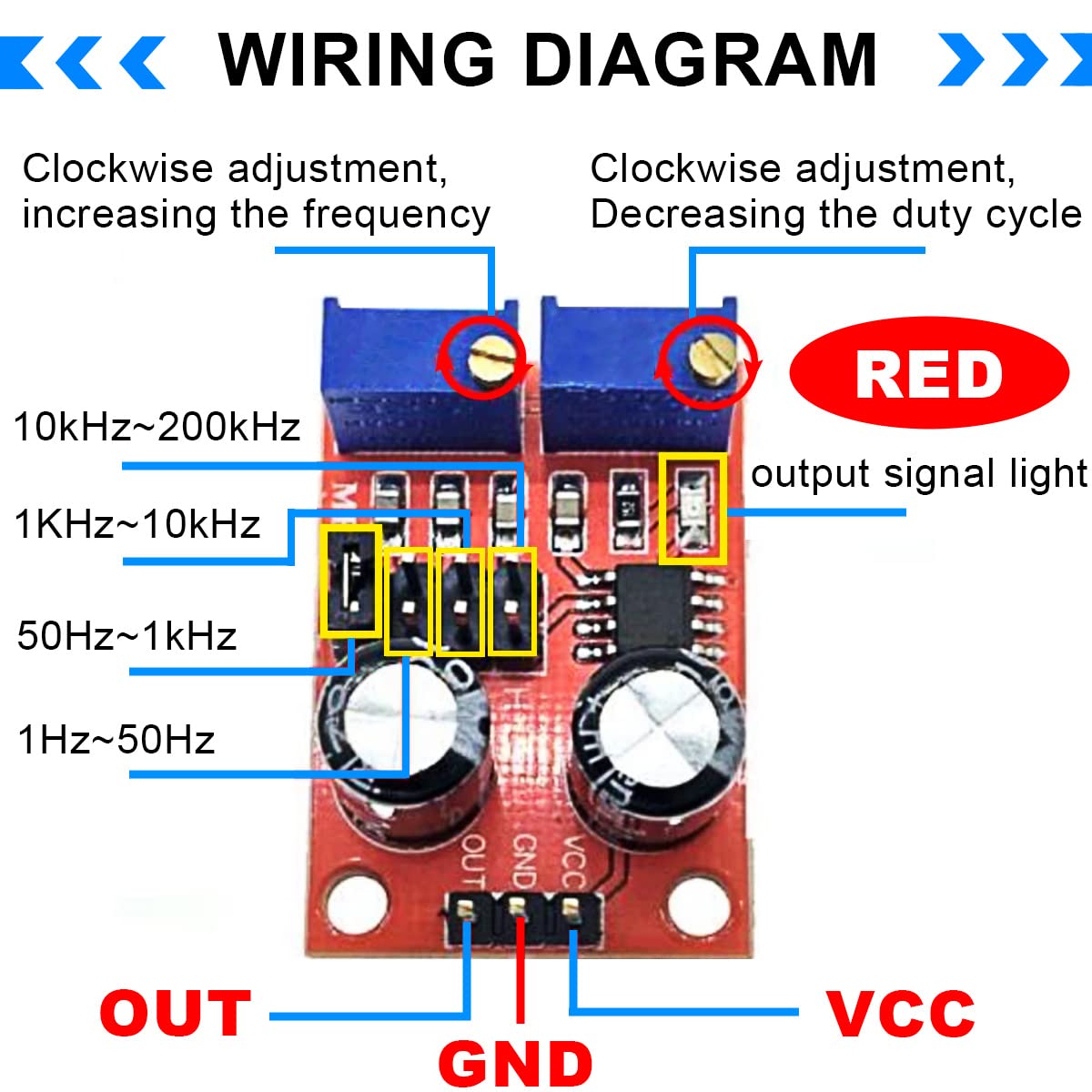
Image 5.1: Wiring Diagram. This diagram illustrates the connections for VCC (power input), GND (ground), and OUT (signal output). It also shows the locations of the frequency range jumpers and adjustment potentiometers.
Spojení:
- VCC: Connect to your DC power supply positive terminal (5V-15V).
- GND: Connect to your DC power supply negative (ground) terminal.
- VEN: This is the square wave signal output. Connect it to your desired circuit or device.
Frequency Range Selection:
The module features four jumpers to select the desired frequency range:
- 1Hz ~ 50Hz
- 50Hz ~ 1kHz
- 1kHz ~ 10kHz
- 10kHz ~ 200kHz
Select the appropriate range by placing the jumper cap on the corresponding pins.
6. Provoz
Once the module is powered and connected, you can adjust the output signal using the onboard potentiometers.
Nastavení frekvence
The potentiometer labeled for frequency adjustment (typically the left blue potentiometer as shown in Image 5.1) controls the output frequency within the selected range. Turning it clockwise will increase the frequency.
The period (T) of the output signal is determined by the formula: T = 0.7 * (RA + 2RB) * C, where RA and RB are adjustable resistances (0 to 10K), and C is the capacitance value determined by the selected frequency range:
- Low frequency: C = 0.001uF
- Intermediate frequency: C = 0.1uF
- Medium-high frequency: C = 1uF
- High frequency: C = 100uF
Duty Cycle Adjustment
The potentiometer labeled for duty cycle adjustment (typically the right blue potentiometer as shown in Image 5.1) controls the duty cycle of the output signal. Turning it clockwise will decrease the duty cycle.
Note: Adjusting the duty cycle may also affect the frequency, as these parameters are interdependent in the NE555 timer circuit configuration.
Výstupní LED indikátor
The module includes an LED indicator (red LED in Image 5.1) that visually confirms the output signal. The LED illuminates when the output is at a low level and turns off when the output is at a high level. For lower frequencies, the LED will visibly flash, indicating the pulse rate.
7. Aplikace
The NE555 Pulse Frequency Duty Cycle Adjustable Module is suitable for a variety of electronic projects and tasks:

Image 7.1: Scope of Application. This image illustrates the module being used in an electronics workshop setting, highlighting its versatility.
- Square Wave Signal Generation: Ideal for experimental development and testing of electronic circuits.
- Stepper Motor Driver: Can generate square wave signals to drive stepper motor controllers.
- Microcontroller (MCU) Pulse Generation: Provides adjustable pulses for various MCU applications.
- Řízení obvodu: Generates adjustable pulses to control other related electronic circuits.
8. Schéma modulu
For advanced users and troubleshooting, the schematic diagram of the NE555 Pulse Generator Module is provided below.

Image 8.1: NE555 Square Wave Pulse Generator Module Schematic. This diagram shows the internal connections of the NE555 IC, potentiometers, capacitors, and output LED.
9. Řešení problémů
If you encounter issues with the module, consider the following troubleshooting steps:
- Žádný výstupní signál:
- Check power connections (VCC and GND) for correct polarity and voltage (5V-15V DC).
- Ensure the jumper for the frequency range is correctly placed.
- Verify that the potentiometers are not set to their extreme ends, which might result in a very low or very high frequency that is difficult to observe.
- Check the output LED for any activity.
- Incorrect Frequency/Duty Cycle:
- Confirm the correct frequency range jumper is selected.
- Adjust the frequency and duty cycle potentiometers slowly.
- Remember that duty cycle adjustment can influence frequency.
- Přehřátí modulu:
- Zajistěte vstupní objtage nepřesahuje 15 V DC.
- Verify that the output is not short-circuited or drawing excessive current.
10. Údržba
The NE555 Pulse Frequency Duty Cycle Adjustable Module requires minimal maintenance. Follow these guidelines to ensure its longevity:
- Keep the module clean and free from dust and debris. Use a soft, dry brush or compressed air if necessary.
- Modul skladujte v suchém a chladném prostředí, mimo dosah přímého slunečního záření a extrémních teplot.
- Avoid physical shock or excessive force on the components, especially the potentiometers and jumper pins.
- Pravidelně kontrolujte spoje, zda nevykazují známky opotřebení nebo koroze.
11. Záruka a podpora
For warranty information or technical support regarding your DAOKAI NE555 Pulse Frequency Duty Cycle Adjustable Module, please refer to the seller's documentation or contact the point of purchase. Keep your purchase receipt as proof of purchase.