1. Úvod
This manual provides detailed instructions for the installation, operation, and maintenance of your BooiParts G31T-LM V1.0 Desktop Motherboard. Please read this manual thoroughly before proceeding with installation to ensure proper setup and to prevent damage to the components.
2. Bezpečnostní informace
- Před instalací nebo demontáží jakýchkoli součástí vždy odpojte napájecí kabel ze zásuvky.
- Wear an anti-static wrist strap or frequently touch a grounded metal object to discharge static electricity before handling the motherboard or other components. Static electricity can damage sensitive electronic parts.
- Základní desku držte za okraje, abyste se nedotkli citlivých součástek.
- Před zapnutím systému se ujistěte, že jsou všechny kabely správně a bezpečně připojeny.
- Nevystavujte základní desku vlhkosti ani extrémním teplotám.
3. Obsah balení
Ověřte, zda jsou v balení všechny položky. Pokud některé položky chybí nebo jsou poškozené, kontaktujte prodejce.
- BooiParts G31T-LM V1.0 Desktop Motherboard
- Štít I/O (může být součástí balení)
- SATA Data Cable (may be included)
- Uživatelská příručka (tento dokument)
4. Konec produktuview
The BooiParts G31T-LM V1.0 motherboard is designed for Intel LGA 775 processors and supports DDR2 memory. Below are key components and their locations.
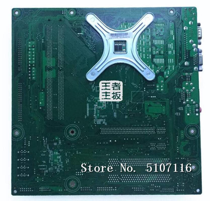
Obrázek 4.1: Nahoru view of the BooiParts G31T-LM V1.0 motherboard. This image highlights the central LGA 775 CPU socket, two DDR2 RAM slots to its right, and various expansion slots (PCIe and PCI) below the CPU area. Power connectors and SATA ports are also visible along the edges.

Obrázek 4.2: Úhlové view of the BooiParts G31T-LM V1.0 motherboard. This perspective provides a clearer view of the rear I/O panel, including PS/2 ports, serial port, VGA output, USB ports, Ethernet port, and audio jacks. Key components like the chipset heatsink and power delivery components are also visible.
4.1 klíčové komponenty
- Patice procesoru LGA 775: For Intel Core 2 Duo and Pentium D processors.
- Sloty DDR2 DIMM: Two slots supporting up to 8GB DDR2 memory.
- Slot PCI Express: Pro grafické karty.
- PCI Slots: For other expansion cards.
- SATA Port: For connecting storage devices.
- Zadní I/O panel: Includes PS/2 ports, USB ports, VGA, LAN, and audio jacks.
5. Nastavení
5.1 Příprava
- Ujistěte se, že je skříň vašeho počítače kompatibilní se základními deskami formátu Micro-ATX.
- Gather all necessary components: CPU, CPU cooler, DDR2 RAM, power supply, storage devices, and graphics card (if not using integrated graphics).
5.2 Instalace CPU
- Vyhledejte patici LGA 775 na základní desce.
- Zvedněte páčku zátěže a otevřete kryt patice procesoru.
- Carefully align the CPU with the socket, ensuring the notches on the CPU match the keys on the socket. Do not force the CPU into place.
- Zavřete kryt zásuvky a zatlačte páku nabíjení dolů, dokud nezapadne na místo.
5.3 CPU Cooler Installation
Apply thermal paste to the CPU if not pre-applied on the cooler. Install the CPU cooler according to its manufacturer's instructions, ensuring it is securely fastened and the fan cable is connected to the CPU_FAN header on the motherboard.
5.4 Instalace RAM
- Otevřete klipy na obou koncích slotů DDR2 DIMM.
- Zarovnejte modul RAM se slotem a ujistěte se, že zářez na modulu odpovídá výstupku ve slotu.
- Pevně zatlačte na oba konce modulu RAM, dokud klipsy nezacvaknou na své místo.
5.5 Motherboard Installation into Case
- Nainstalujte kryt I/O do zadního otvoru skříně počítače.
- Opatrně vložte základní desku do skříně a zarovnejte otvory pro šrouby na základní desce s distančními výčnělky ve skříni.
- Zajistěte základní desku šrouby. Nepřetahujte je.
5.6 Připojení napájení
- Připojte 24pinový ATX napájecí konektor ze zdroje k odpovídajícímu konektoru na základní desce.
- Connect the 4-pin ATX 12V power connector (CPU power) to its header near the CPU socket.
5.7 Připojení úložných zařízení
Connect your SATA storage devices (HDD/SSD) to the SATA port on the motherboard using a SATA data cable. Connect the power cable from your power supply to the storage device.
5.8 Připojení konektorů na předním panelu
Connect the front panel cables (Power SW, Reset SW, HDD LED, Power LED, USB, Audio) from your case to the corresponding headers on the motherboard. Refer to the motherboard's silkscreen labels for correct pin orientation.
5.9 Připojení periferních zařízení
Připojte klávesnici, myš, monitor a další periferní zařízení k příslušným portům na zadním panelu I/O.
6. Návod k obsluze
6.1 První spuštění
After completing all connections, turn on your power supply and press the power button on your computer case. The system should power on, and you should see a display on your monitor. If not, refer to the Troubleshooting section.
6.2 Nastavení BIOSu/UEFI
During startup, press the designated key (usually DEL or F2) to enter the BIOS/UEFI setup utility. Here you can configure system settings, boot order, and monitor hardware status.
7. Údržba
- Čištění: Pravidelně čistěte prach ze základní desky a jejích součástí pomocí stlačeného vzduchu. Před čištěním se ujistěte, že je systém vypnutý a odpojený od sítě.
- Aktualizace BIOSu: Zkontrolujte výrobce website for BIOS updates. Only update the BIOS if necessary and follow the instructions carefully to avoid system instability.
- Správa kabelů: Zajistěte úhledné vedení kabelů, aby se zlepšilo proudění vzduchu a zabránilo se rušení.
8. Řešení problémů
8.1 Bez napájení
- Zkontrolujte, zda je zdroj napájení zapnutý a správně připojený k základní desce (24pinový a 4pinový konektor).
- Ujistěte se, že je kabel vypínače na předním panelu správně připojen ke konektoru základní desky.
- Otestujte napájecí zdroj pomocí jiného systému nebo testeru napájecích zdrojů.
8.2 Žádný displej
- Verify that the monitor is connected to the correct video output (onboard VGA or discrete graphics card).
- Reseat the RAM modules. Incorrectly seated RAM is a common cause of no display.
- If using a discrete graphics card, ensure it is properly seated in its PCIe slot and has adequate power connected.
- Zkuste bootovat pouze s jednou RAM pamětí.
8.3 Nestabilita/pády systému
- Zkontrolujte teplotu CPU a GPU. Přehřátí může způsobit nestabilitu.
- Ujistěte se, že všechny ovladače jsou aktuální.
- Spusťte diagnostické nástroje paměti a zkontrolujte, zda není RAM vadná.
- Ověřte napájecí zdrojtage je dostatečné pro všechny komponenty.
9. Specifikace
The following table outlines the key specifications for the BooiParts G31T-LM V1.0 Motherboard.
| Funkce | Specifikace |
|---|---|
| Značka | BooiParts |
| Název modelu | G31T-LM V1.0 |
| Zásuvka CPU | LGA 775 |
| Kompatibilní procesory | Intel Core 2 Duo, Intel Pentium D |
| Typ čipové sady | Intel G31 |
| Technologie paměti RAM | DDR2 |
| K dispozici paměťové sloty | 2 |
| Kapacita paměti (max.) | 8 GB |
| Rozhraní grafické karty | PCI Express |
| Total SATA Ports | 1 |
| Total PCIe Ports | 2 |
| Typ hlavního napájecího konektoru | 24-pin |
| Kompatibilní zařízení | Osobní počítač |
| Číslo modelu | T4900V 53Y3282 45C2882 |
10. Záruka a podpora
Informace o záruce a technickou podporu naleznete v dokumentaci dodané s vaším nákupem nebo se obraťte na svého prodejce. Uschovejte si doklad o koupi pro případné reklamace.