Zavedení
This manual provides comprehensive instructions for the Walfront DC 12V 1-10 Second Adjustable Timer Relay Module. It covers product overview, specifications, setup, operation, maintenance, and troubleshooting to ensure safe and effective use of the module.
Bezpečnostní informace
Please read and understand all safety precautions before installing or operating this module. Failure to do so may result in damage to the module, connected equipment, or personal injury.
- Před jakýmkoli zapojením nebo nastavením kabeláže vždy odpojte napájení.
- Zajistěte vstupní objtage (DC 12V) is correct and stable. Incorrect voltagMůže to poškodit modul.
- Avoid short circuits on the input or output terminals.
- Nepřekračujte specifikovaný proud a objemtage ratings for the relay contacts (10A 250VAC / 10A 30V DC).
- Chraňte modul před vlhkostí, prachem a extrémními teplotami.
- If you are unsure about any aspect of installation or operation, consult a qualified technician.
Konec produktuview
The Walfront DC 12V 1-10 Second Adjustable Timer Relay Module is a high-precision, stable, and reliable timing relay designed for various applications requiring timed control. It features an adjustable delay range and a trigger button for activation.
Vlastnosti
- High-precision, stable, and reliable timer relay module.
- Supports reverse input protection.
- Equipped with a trigger button switch.
- Adjustable time range from 1 to 10 seconds via potentiometer.
- Widely applicable in timer operation equipment, robotics, intelligent product development, automation, PLC development, smart home anti-theft alarm delay, and electronic development.
Komponenty
The module consists of a circuit board with a relay, a potentiometer for time adjustment, input/output terminals, and an external trigger button.
Specifikace
| Atribut | Hodnota |
|---|---|
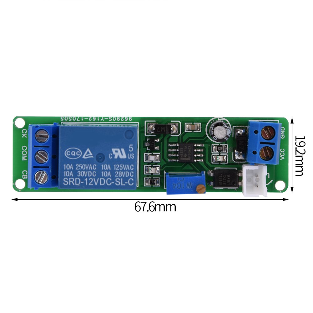
| Rozměry produktu (D x Š x V) | 10.3 x 6 x 2.52 cm |
| Hmotnost | 23 gramů |
| Výrobce | Walfront |
| Číslo modelu | Walfrontaefdzo62yn6177 |
| Vstupní objemtage | DC 12V |
| Časový rozsah | 1 to 10 seconds (adjustable) |
| Hodnocení kontaktu relé | 10A 250VAC / 10A 30V DC |
| Země původu | Čína |
Nastavení
Schéma zapojení a připojení
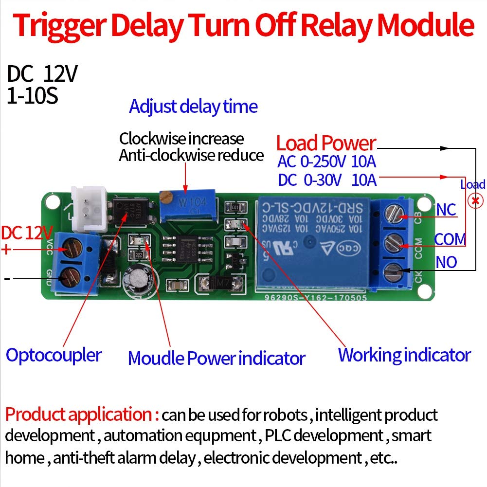
Refer to the diagram in the Product Overview section for visual guidance. The module has clearly labeled terminals for power input and relay output.
- Příkon: Connect DC 12V power to the VCC (+) and GND (-) terminals. Ensure correct polarity. The module includes reverse input protection.
- Reléový výstup: The relay has three terminals: NC (Normally Closed), COM (Common), and NO (Normally Open). Connect your load according to your application's requirements.
- For a load that should be OFF normally and turn ON after delay: Connect one side of the load to COM and the other side to NO.
- For a load that should be ON normally and turn OFF after delay: Connect one side of the load to COM and the other side to NC.
Počáteční konfigurace
After wiring, apply DC 12V power to the module. The power indicator LED should illuminate, indicating the module is receiving power.
Návod k obsluze
Úprava doby zpoždění
The delay time of the module can be adjusted from 1 to 10 seconds using the onboard potentiometer (labeled 'W104' in the diagram).
- Na zvýšení the delay time, turn the potentiometer clockwise.
- Na pokles the delay time, turn the potentiometer anti-clockwise.
- If a longer delay time is required beyond 10 seconds, it is possible to replace the existing capacitor or potentiometer with components of larger values. This modification should only be performed by experienced individuals.
Triggering the Relay
The module operates by triggering the relay and then initiating a delay before turning off the connected load.

- Ensure the module is powered on and correctly wired to your load.
- Press the external trigger button.
- Upon pressing the button, the load connected to the relay will turn ON (or OFF, depending on NC/NO connection).
- After the set delay time (1-10 seconds) has elapsed, the load will automatically turn OFF (or ON).
Údržba
The Walfront Timer Relay Module is designed for reliable operation with minimal maintenance. Follow these guidelines to ensure its longevity:
- Udržujte modul čistý a bez prachu a nečistot. K čištění používejte měkký, suchý hadřík.
- Ensure all wiring connections remain secure. Loose connections can lead to intermittent operation or damage.
- Avoid exposing the module to excessive vibration or mechanical shock.
- Store the module in a dry, temperature-controlled environment when not in use.
Odstraňování problémů
If you encounter issues with your Walfront Timer Relay Module, refer to the table below for common problems and solutions.
| Problém | Možná příčina | Řešení |
|---|---|---|
| Module does not power on (no indicator light) | Žádné napájení; Nesprávná hlasitosttage; Reverse polarity; Faulty power supply. | Check power connections (VCC, GND). Ensure DC 12V is supplied. Verify polarity. Test power supply. |
| Relay does not activate after trigger | Faulty trigger button; Incorrect wiring to load; Load issue; Potentiometer set to minimum delay. | Check trigger button functionality. Verify load wiring (COM, NO/NC). Test the load independently. Adjust potentiometer to a visible delay time. |
| Delay time is incorrect or inconsistent | Potentiometer setting; Environmental factors; Component degradation. | Adjust the potentiometer carefully. Ensure stable operating environment. If issue persists, module may require replacement. |
| Load remains ON/OFF indefinitely | Relay contacts stuck; Module fault. | Disconnect power and check relay contacts. If the relay is physically stuck, it may need replacement. If not, the module may be faulty. |
Záruka a podpora
For warranty information or technical support, please refer to the documentation provided at the point of purchase or contact Walfront customer service directly. Keep your purchase receipt as proof of purchase.


