
1. Úvod
This manual provides detailed instructions for the DEVMO DC 5V/12V 1 Channel Relay Board, Model JZ801. This programmable multifunctional module is designed for various timing and control applications, offering flexible operation modes and robust performance.
Mezi klíčové vlastnosti patří:
- Široký vstupní objemtage range: 6-30V, with micro USB 5.0V power supply option.
- Adjustable timing range: 0.1 seconds to 999 minutes.
- Vysoký objemtage level trigger (3.0V-24V).
- Output capability: DC 0-30V 5A or AC 0-220V 5A.
- Opto-isolator for enhanced anti-interference.
- Reverse connect protection.
- Automatic parameter saving upon power-off.
- Sleep mode for power saving.
2. Obsah balení
Prosím, ověřte, zda jsou v balení přítomny všechny položky:
- 1x DEVMO 1 Channel Multi-functional Time Delay Relay Board (blue board)
- 1x USB to Micro USB Power Line
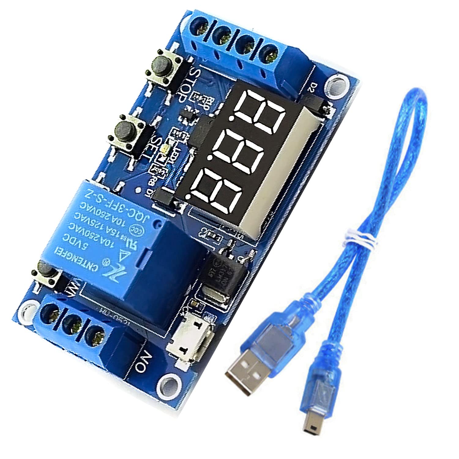
Figure 2.1: DEVMO JZ801 Relay Board and USB to Micro USB Power Line.
This image displays the DEVMO JZ801 1 Channel Relay Board, a blue circuit board with a 3-digit LED display, three control buttons (SET, STOP), a relay, and screw terminals for connections. A blue USB to Micro USB cable is also shown alongside the board.
3. Konec produktuview a Připojení
Familiarize yourself with the components and connection points of the relay board.

Obrázek 3.1: Nahoře view of the DEVMO JZ801 Relay Board.
Tento obrázek poskytuje jasný pohled shora dolů view of the blue DEVMO JZ801 relay board, highlighting the 3-digit LED display, the three push buttons (SET, STOP, and one unmarked), the relay component, and the screw terminals for power input and relay output.

Obrázek 3.2: Spodní část view of the DEVMO JZ801 Relay Board.
This image shows the underside of the DEVMO JZ801 relay board, revealing the solder points, circuit traces, and the model number 'JZ-801' printed on the PCB. It also indicates the power input terminals (6.0~30.0V, GND) and trigger input (Trigger, GND_TO).
3.1 Vstup napájení
- DC vstup: Connect a DC power source between 6V and 30V to the screw terminals labeled 6.0~30.0V (pozitivní) a GND (záporný).
- Vstup micro USB: Alternatively, power the module using a 5V Micro USB power supply connected to the Micro USB port.
3.2 Spouštěcí vstup
- The trigger source requires a high voltage level between 3.0V and 24V.
- Connect the trigger signal to the terminal labeled Spoušť and the ground reference to GND_TO.
3.3 Reléový výstup
The relay provides three terminals for connecting your load:
- NE (normálně otevřeno): This terminal is open (disconnected) when the relay is de-energized and closed (connected to COM) when energized.
- COM (běžné): Toto je společný terminál pro reléový spínač.
- NC (normálně zavřeno): This terminal is closed (connected to COM) when the relay is de-energized and open (disconnected from COM) when energized.
The relay can control devices within DC 0-30V 5A or AC 0-220V 5A.
4. Návod k obsluze
4.1 Main Interface and Display
When the module is off, the display shows "000" (no decimal point). During operation, the display will show a decimal point, indicating active status.

Figure 4.1: DEVMO JZ801 Relay Board with LED display and control buttons.
This image highlights the 3-digit LED display and the three control buttons (SET, STOP, and an unlabeled button) on the DEVMO JZ801 relay board, which are used for programming and operating the module.
4.2 Definice parametrů
- OP: Turn-On Time (duration the relay is energized).
- CL: Turn-Off Time (duration the relay is de-energized).
- PROKRESLIT: Cycle Index (number of cycles). "---" indicates an limitless cycle.
These parameters are independent for each work mode but share the same values across different modes once set.
4.3 Nastavení časování
To set timing values:
- Enter the mode selection screen (see Section 4.4).
- After setting the parameter values (OP, CL, LOP), short press the ZASTÁVKA button to select the time range for the currently displayed parameter.
- Available time ranges:
- XXX: 1 second to 999 seconds (e.g., 123 for 123 seconds).
- XX.X: 0.1 seconds to 99.9 seconds (e.g., 12.3 for 12.3 seconds).
- X.X.X.: 1 minute to 999 minutes (e.g., 1.2.3. for 123 minutes).
4.4 Work Mode Selection
Dlouze stiskněte SOUBOR key to enter or exit the mode selection screen. In this screen, you can choose different operational modes for the relay.
4.5 Relay Enable/Disable Mode
From the main interface, a short press of the ZASTÁVKA button will toggle the relay between ON and OFF states, effectively enabling or disabling its operation.
4.6 Režim spánku
To activate or deactivate sleep mode:
- Dlouze stiskněte ZASTÁVKA tlačítko na dvě sekundy.
- Release the button to switch between Cl (normal mode) and O-d (sleep mode) states.
In sleep mode, if there is no operation for five minutes, the digital display automatically turns off to save power. Press any key to turn the display back on.
5. Údržba
- Udržujte modul čistý a bez prachu a vlhkosti.
- Nevystavujte modul extrémním teplotám nebo přímému slunečnímu záření.
- Ensure all connections are secure to prevent intermittent operation.
- Do not attempt to modify the circuit board, as this may void any warranty and cause damage.
6. Řešení problémů
- Modul se nezapíná: Ověřte napájení objtage is within the 6-30V range for DC input, or ensure the Micro USB cable is properly connected to a 5V source. Check for correct polarity on DC input.
- Relay not triggering: Ensure the trigger signal voltage is between 3.0V and 24V. Check the trigger input connections for proper contact. Verify the selected work mode and timing parameters are correctly configured.
- Nesprávné načasování: Double-check the OP, CL, and LOP parameter settings. Ensure the correct time range (seconds, 0.1 seconds, minutes) is selected for each parameter.
- Displej je vypnutý: The module might be in sleep mode. Press any button to reactivate the display. If not in sleep mode, check power supply.
- Přerušovaný provoz: Check all wiring connections for looseness. Ensure the load current does not exceed the relay's maximum rating (DC 0-30V 5A or AC 0-220V 5A). The built-in opto-isolator helps reduce interference, but ensure your environment is free from excessive electrical noise.
7. Specifikace
| Funkce | Specifikace |
|---|---|
| Číslo modelu | JZ801 |
| Rozměry (D x Š x V) | 6.2 cm x 3.8 cm x 1.7 cm (2.44 x 1.50 x 0.67 palce) |
| Práce svtage | DC 6-30V (supports Micro USB 5.0V power supply) |
| Spouštěcí zdroj | Vysoký objemtage level trigger (3.0V-24V) |
| Výstupní schopnost | DC 0-30V 5A or AC 0-220V 5A |
| Klidový proud | 20 mA |
| Pracovní proud | 50 mA |
| Životnost | Více než 100,000krát |
| Pracovní teplota | -40°C až +85°C |
| Rozsah časování | 0.1 sekundy až 999 minut (nastavitelné) |
| Hmotnost | 0.06 kilogramu (přibližně 2.08 unce) |
8. Záruka a podpora
Warranty information for the DEVMO DC 5V/12V 1 Channel Relay Board is typically provided at the point of purchase or can be found on the manufacturer's official webwebu. Konkrétní záruční podmínky naleznete v dokumentaci k nákupu.
For technical support, troubleshooting assistance, or further inquiries, please contact your retailer or the DEVMO customer service department through their official channels. Ensure you have your product model number (JZ801) and purchase details available when seeking support.