1. Úvod
This instruction manual provides essential information for the safe and efficient use of the Walfront DC-DC Boost Converter Module. Please read this manual thoroughly before installation and operation to ensure proper functionality and to prevent damage to the module or connected devices.
The Walfront DC-DC Boost Converter Module is a compact step-up voltage regulator designed to convert a lower DC input voltage to a higher, stable DC output voltage. It is suitable for various applications requiring a boosted power supply.
2. Klíčové vlastnosti
- Vysoká účinnost: Operating frequency of 1MHz with up to 93% efficiency.
- Ochranné vlastnosti: Zahrnuje nadproud, přepětítage, ochrana proti zkratu a přehřátí.
- Wide Input Voltage Rozsah: Přijímá stejnosměrné napětí 2.6 V až 5.5 V.
- Selectable Output Voltages: Provides DC 5V, 6V, 9V, or 12V (optional, depending on model configuration).
- Kompaktní design: Small form factor for integration into various projects.
3. Nastavení a instalace
3.1 Identifikace součásti
Familiarize yourself with the module's components and pin assignments.
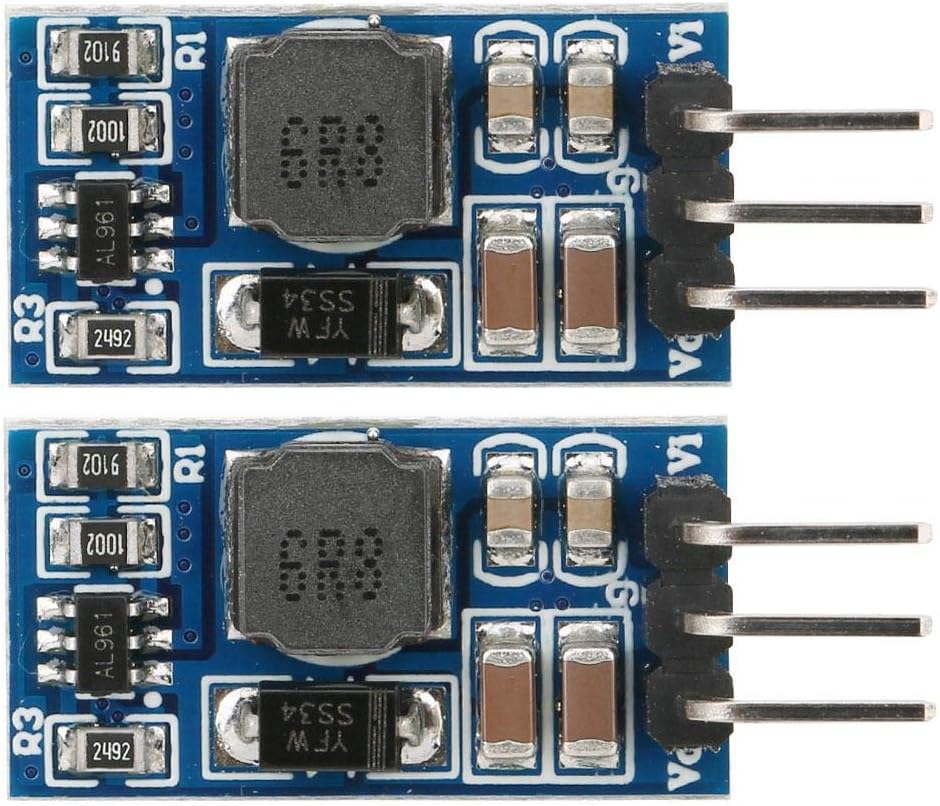
Obrázek 1: Nahoře view of two Walfront DC-DC Boost Converter Modules. Each module features an inductor, various capacitors, and integrated circuits on a blue PCB. Pins for connection are visible on the right side.

Obrázek 2: Úhlové view of the Walfront DC-DC Boost Converter Module, showcasing its compact dimensions and the arrangement of its surface-mount components.
3.2 Popis kolíku
- Vi: Input positive (+) voltage. Connect your DC power source here.
- GND: Input and Output negative (-) / Ground. This is the common ground for both input and output.
- hlas: Output positive (+) voltage. Connect your load requiring the boosted voltage tady.
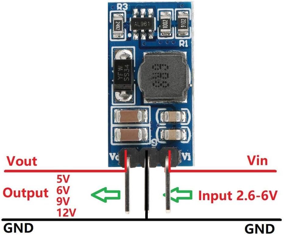
Figure 3: Connection diagram for the boost converter module. It illustrates the input (Vin) and output (Vout) voltage pins, along with the common ground (GND) connection. Input voltage range is 2.6-6V, and output options are 5V, 6V, 9V, 12V.
3.3 Výstupní objemtage Selection (for adjustable models)
Some models allow for output voltage selection via solder pads or external resistors. The specific model (WALFRONTi1zh84cdtw-12) is listed as 6V, with other options available. If your module has selectable output pads, ensure the correct pad is soldered or configured for your desired output voltage (5 V, 6 V, 9 V, 12 V).
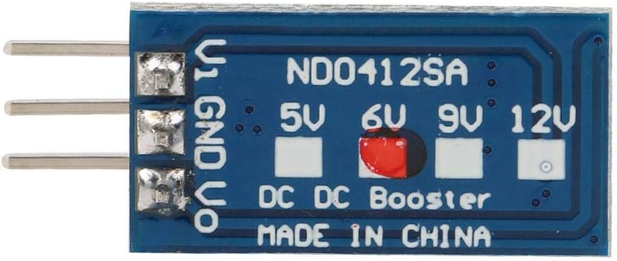
Obrázek 4: Spodní část view of the module, displaying solder pads labeled for 5V, 6V, 9V, and 12V output selection. A red mark indicates the 6V selection for this specific module.
For models where output voltage is set by an external resistor (R1), refer to the following formula and table:
R1(KΩ) = 10 * (Vout / 0.6 - 1)

Figure 5: Diagram showing the location of resistor R1 for output voltage setting and R3 for current limit programming. A table provides example R1 values for different output voltages (3.7V, 4.2V, 5V, 6V, 7.5V, 9V, 10V, 12V).
3.4 Current Limit Programming
The R3 resistor programs the peak switch current. The resistor value should be between 10kΩ and 100kΩ. The current limit will be set from 2.5A to 0.5A according to the formula:
Iin = 48000 / R3
Kde jáin is the input current limit in Amperes and R3 is the resistance in Ohms.
4. Provoz
4.1 Připojení napájení
- Ensure your input power source is within the specified range of DC 2.6V to 5.5V.
- Connect the positive terminal of your input power source to the Vi kolík.
- Connect the negative terminal (ground) of your input power source to the GND kolík.
4.2 Připojení zátěže
- Connect the positive terminal of your load to the Vo kolík.
- Connect the negative terminal (ground) of your load to the GND kolík.
- Verify that your load's voltage requirement matches the output voltage configured on the module.
4.3 Aspekty výkonu
The module's efficiency can reach up to 93%, but typical efficiency ranges from 84% to 91%. Performance may vary based on input voltage, výstupní objemtage, and load current. Refer to the specifications for detailed performance data.
Example performance data for 6V output:
| Vstupní objemtage | Vstupní proud | Výstupní objemtage | Výstupní proud |
|---|---|---|---|
| 2.6V | 1.35A | 6V | 0.48A |
| 3V | 1.63A | 6V | 0.67A |
| 3.3V | 1.76A | 6V | 0.80A |
| 3.7V | 1.74A | 6V | 0.90A |
| 4.2V | 1.65A | 6V | 1.00A |
| 5V | 1.62A | 6V | 1.20A |
Table 1: Typical performance data for 6V output. Measurement results are for reference only.
5. Údržba
The Walfront DC-DC Boost Converter Module is designed for reliable operation and generally requires minimal maintenance.
- Čištění: Keep the module free from dust and debris. If cleaning is necessary, use a soft, dry brush or compressed air. Do not use liquids or solvents.
- Inspekce: Periodically inspect the module for any signs of physical damage, loose connections, or discoloration of components.
- Podmínky prostředí: Ensure the module operates within its specified temperature range (-40°C to +85°C) and avoid excessive humidity.
6. Řešení problémů
If you encounter issues with your DC-DC Boost Converter Module, refer to the following common problems and solutions:
| Problém | Možná příčina | Řešení |
|---|---|---|
| Žádný výstupní objemtage. |
|
|
| Výstupní objemtage je nesprávné. |
|
|
| Modul se nadměrně zahřívá. |
|
|
7. Specifikace
| Parametr | Hodnota |
|---|---|
| Číslo modelu | WALFRONTi1zh84cdtw-12 |
| Vstupní objemtage (Vi) | DC 2.6V ~ 5.5V |
| Výstupní objemtage (Vo) | DC 5V / 6V / 9V / 12V (Optional, 6V for this model) |
| Maximum Output Current (6V) | 1200 mA (1.2A) |
| Pracovní frekvence | 1 MHz |
| Účinnost | Up to 93% (typically 84%-91%) |
| Klidový proud | 190 uA |
| Current Limit Program | 0.5A - 2.5A (Default 1.8A) |
| Rozsah provozních teplot | -40 °C ~ +85 °C |
| Rozsah skladovacích teplot | -65 °C ~ +150 °C |
| Dimensions (approx., no Pin) | 21 x 11 x 4 mm (0.8 x 0.4 x 0.2 palce) |
| Weight (approx., with Pin) | 1.5 g |
| Ochranné funkce | Nadproud, Nadproudtage, Short-circuit, Over-temperature |
8. Informace o záruce
Specific warranty details for Walfront products may vary. Please refer to the retailer's return policy or contact Walfront customer support for information regarding warranty coverage and terms.
As per Amazon's buybox winner information, a return policy of 30 days for refund/replacement is typically available.
9. Zákaznická podpora
For technical assistance, product inquiries, or support, please contact Walfront customer service through their official channels or the retailer from whom the product was purchased.
You can visit the Walfront Store on Amazon for more information: Walfront Amazon Store