1. Úvod
The Walfront HT201 is a passive attenuator designed to extend the measurement capabilities of your oscilloscope. It provides a 20:1 attenuation ratio, allowing your oscilloscope to safely measure higher voltages than its direct input range. This device is particularly useful for automotive diagnostics, enabling the measurement of fuel injector and primary ignition waveforms.

Figure 1: The Walfront HT201 Passive Attenuator, a compact black device with BNC connectors on both ends, labeled "ATTENUATOR HT-201" with "Attenuation: 20:1" and "Bandwidth: 10MHz".
2. Bezpečnostní informace
Please read and understand the following safety precautions before using the HT201 attenuator. Failure to follow these instructions may result in damage to the device, oscilloscope, or personal injury.
- svtage Limity: The HT201 is designed to attenuate high voltages. Ensure that the input voltage does not exceed the maximum specified voltage for the attenuator (300V).
- Application Specific Use: This attenuator is suitable for measuring inductive signals such as fuel injector and primary ignition waveforms.
- DŮLEŽITÉ VAROVÁNÍ: Do NOT use this attenuator for secondary ignition tests. Secondary ignition voltages are significantly higher and can damage the attenuator and your oscilloscope.
- Správné připojení: Always ensure secure and correct connections between the attenuator, the signal source, and the oscilloscope. Loose connections can lead to inaccurate readings or damage.
- Podmínky prostředí: Use the attenuator in a dry environment, away from moisture, extreme temperatures, and corrosive substances.

Figure 2: An illustration emphasizing the specific use case for the attenuator, stating it can measure fuel injector and primary ignition waveforms, with a critical warning not to use it for secondary ignition tests.
3. Vlastnosti produktu
- Poměr útlumu: Provides a 20:1 attenuation, meaning an input voltage of 20V will be reduced to 1V at the output. This allows oscilloscopes with limited input ranges (e.g., ±20V) to measure much higher voltages.
- šířka pásma: Operates effectively within a 10MHz bandwidth.
- Ochrana proti přetížení vstupu: Designed to provide enhanced input overload protection for your oscilloscope when measuring inductive signals.
- Kompatibilita: Equipped with standard BNC connectors for wide compatibility with most oscilloscopes.
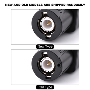
Figure 3: An icon representing input overload protection, highlighting a key safety feature of the HT201 attenuator.
4. Nastavení a připojení
Follow these steps to properly connect the HT201 attenuator to your oscilloscope and the signal source.
- Identifikujte konektory: The HT201 has a male BNC connector on one end and a female BNC connector on the other. The male end typically connects to the signal source, and the female end connects to the oscilloscope's input.
- Connect to Signal Source: Connect the male BNC end of the HT201 attenuator to the signal source you wish to measure (e.g., a test lead from a fuel injector).
- Connect to Oscilloscope: Connect the female BNC end of the HT201 attenuator to the input channel of your oscilloscope. Ensure the connection is firm and secure.
- Nastavení osciloskopu: Adjust your oscilloscope's vertical scale (Volts/Div) to account for the 20:1 attenuation. For example, if the attenuator outputs 1V, the actual signal is 20V. You will need to manually multiply your oscilloscope's reading by 20, or if your oscilloscope supports probe settings, set the probe attenuation to 20X.
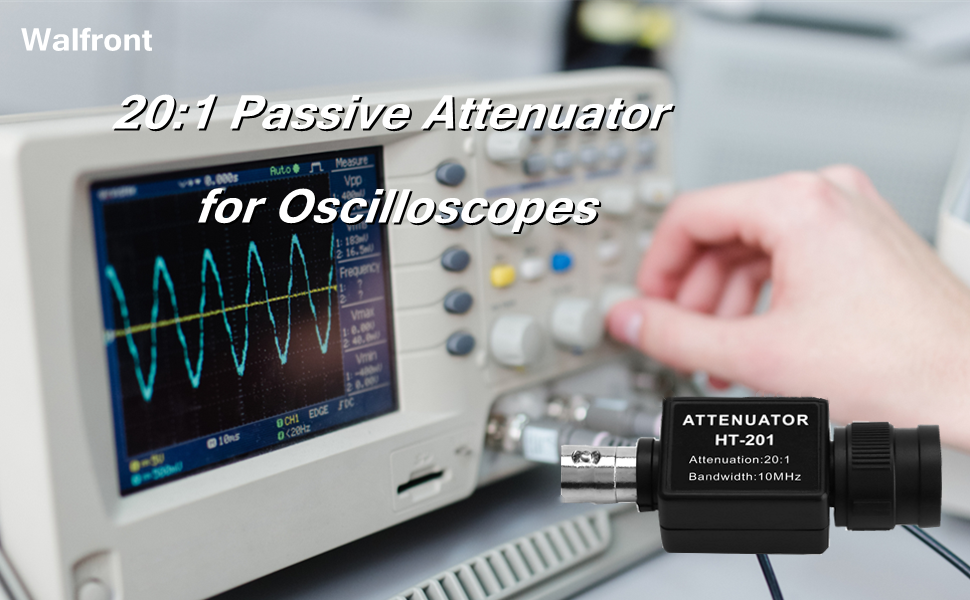
Figure 4: A diagram illustrating the male and female BNC connectors of the HT201 attenuator, indicating which end connects to the signal source and which to the oscilloscope.

Figure 5: A visual comparison between the "New Type" and "Old Type" BNC connectors, indicating that either version may be shipped randomly.
5. Provoz
Once the HT201 attenuator is connected, you can proceed with your measurements. Remember to adjust your oscilloscope settings accordingly.
- Měření signálu: The attenuator allows your oscilloscope to display waveforms from high-voltage sources without damaging the oscilloscope's input circuitry.
- Automobilové aplikace: Specifically, this attenuator is ideal for observing waveforms from fuel injectors and primary ignition coils, which typically involve voltages higher than standard oscilloscope inputs can handle directly.
- Výklad čtení: Always remember that the voltage displayed on your oscilloscope screen is 1/20th of the actual voltage. Multiply the displayed voltage by 20 to get the true voltage zdroje signálu.

Figure 6: A user operating an oscilloscope with the HT201 attenuator connected, demonstrating its use in measuring electrical waveforms.
6. Údržba
The Walfront HT201 attenuator requires minimal maintenance to ensure its longevity and accurate performance.
- Čištění: Use a soft, dry cloth to clean the exterior of the attenuator. Do not use abrasive cleaners or solvents.
- Skladování: Store the attenuator in a cool, dry place, away from direct sunlight and extreme temperatures. Protect the connectors from dust and physical damage.
- Inspekce: Periodically inspect the connectors for any signs of wear, corrosion, or damage. Ensure they are clean and free of debris before each use.
7. Řešení problémů
If you encounter issues while using the HT201 attenuator, consider the following common troubleshooting steps:
- Žádný signál nebo slabý signál:
- Zkontrolujte všechna připojení a ujistěte se, že jsou bezpečná.
- Verify that the signal source is active and producing a signal.
- Ensure your oscilloscope's vertical scale (Volts/Div) is set appropriately. Remember the 20:1 attenuation.
- Zkreslený tvar vlny:
- Check the attenuator's bandwidth (10MHz) against the frequency of your signal. Signals exceeding the bandwidth may appear distorted.
- Ensure the signal voltage does not exceed the attenuator's maximum input voltage.
- Inspect the attenuator and cables for any physical damage.
- Nesprávný svtage čtení:
- Confirm that you are multiplying the oscilloscope's displayed voltage by the correct attenuation factor (20).
- If your oscilloscope has probe settings, ensure it is correctly configured for a 20X probe.
8. Specifikace
| Parametr | Hodnota |
|---|---|
| Model | HT201 |
| Poměr útlumu | 20:1 |
| Šířka pásma | 10 MHz |
| Maximální vstupní objemtage | 300V |
| Typ konektoru | BNC (Male to Female) |
| Výrobce | Walfront |

Figure 7: Dimensions of the HT201 attenuator, showing a length of 61mm (2.4 inches), and connector widths of 17mm (0.7 inches) and 21mm (0.8 inches).
9. Záruka a podpora
Walfront products are manufactured to high-quality standards. For any questions regarding the HT201 Passive Attenuator, please contact your retailer or Walfront customer support. Please refer to your purchase documentation for specific warranty terms and conditions.
For further assistance, you may visit the Walfront store on Amazon: Walfront Store