1. Úvod
This manual provides detailed instructions for the Walfront DC 12V Adjustable Delay Timer Relay Module. This module is designed to provide a time-delayed turn-off function for various electronic applications. It features an adjustable delay time from 1 to 10 seconds and operates on a 12V DC power supply. Please read this manual thoroughly before installation and operation to ensure correct usage and optimal performance.
2. Bezpečnostní informace
- Zajistěte napájení objtage matches the module's specified input (DC 12V). Incorrect voltagMůže to poškodit modul.
- Do not exceed the maximum load capacity of the relay (AC 250V 10A or DC 30V 10A).
- Exercise caution when working with electrical circuits. Disconnect power before making any connections or adjustments.
- Keep the module away from moisture, extreme temperatures, and corrosive environments.
- This module is not a toy. Keep out of reach of children.
3. Konec produktuview
The Walfront DC 12V Adjustable Delay Timer Relay Module is a compact circuit board with a relay, a potentiometer for time adjustment, and terminal blocks for connections. It includes a trigger button for initiating the delay sequence.

Figure 3.1: Walfront DC 12V Delay Timer Relay Module with its external trigger button.
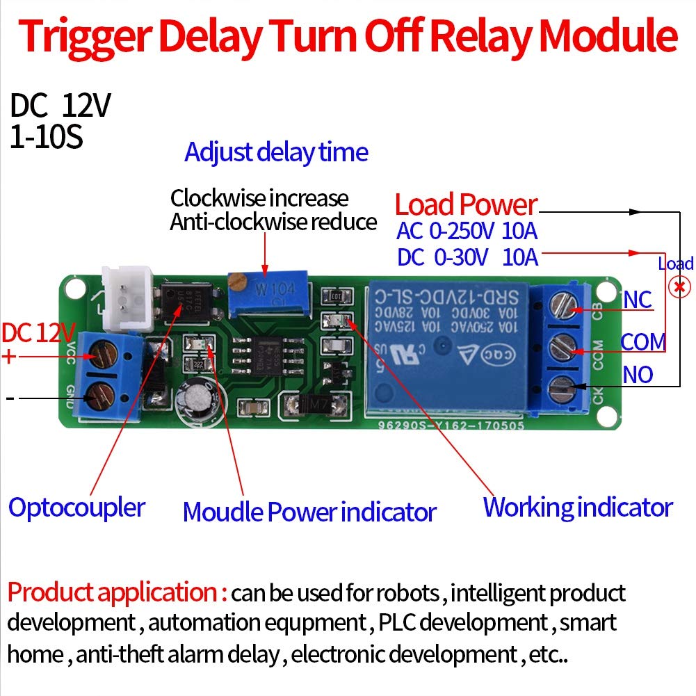
Obrázek 3.2: Detailní view of the module showing the relay, potentiometer, power input, and load output terminals. The image also indicates the optocoupler, module power indicator, and working indicator.
4. Specifikace
| Funkce | Hodnota |
|---|---|
| Pracovní svtage | DC 12V |
| Kapacita zatížení | AC 250V 10A / DC 30V 10A |
| Časový rozsah zpoždění | 1 to 10 seconds (Adjustable) |
| Rozměry | 67.6mm × 19.2mm (2.66" × 0.75") |
| Typ konektoru | Přes díru |
| Typ montáže | Povrchová montáž |
| Provozní režim | Manuál |
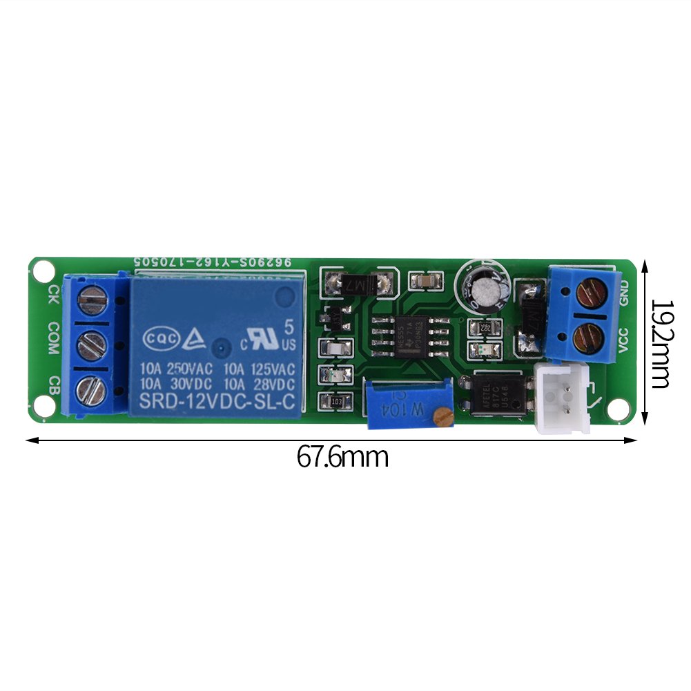
Figure 4.1: Physical dimensions of the module, showing a length of 67.6mm and a width of 19.2mm.
5. Nastavení a zapojení
Follow these steps to correctly set up and wire your delay timer relay module:
- Připojení napájení:
- Připojte DC 12V positive (+) power supply to the VCC terminál.
- Připojte DC 12V negative (-) power supply to the GND terminál.
- Načíst připojení: The relay has three terminals for load connection: ŽÁDNÝ (Normally Open), COM (Common), and NC (Normally Closed).
- For a load that should be VYPNUTO normally and turn ON after the trigger and during the delay, connect one side of the load to COM and the other side to ŽÁDNÝ.
- For a load that should be ON normally and turn VYPNUTO after the trigger and during the delay, connect one side of the load to COM and the other side to NC.
- Ensure the load's power source is connected appropriately and does not exceed the relay's capacity.
- Trigger Button Connection: The module comes with an external trigger button. Connect its two wires to the CK a CB terminals on the module. The polarity for the trigger button does not matter.
- Úprava doby zpoždění: Use a small screwdriver to turn the blue potentiometer (labeled W104) on the module. Turning it clockwise increases the delay time, while turning it counter-clockwise decreases it. The delay time is adjustable from 1 to 10 seconds.
Figure 5.1: Wiring diagram illustrating connections for DC 12V power input (VCC, GND), load output (NO, COM, NC), and trigger input (CK, CB). The potentiometer for delay adjustment is also indicated.
6. Návod k obsluze
Once the module is wired and powered, follow these steps for operation:
- Zapnutí: Apply DC 12V power to the VCC and GND terminals. The module's power indicator LED should illuminate, indicating it is ready.
- Initiate Delay: Press the external trigger button connected to CK and CB.
- Akce relé: Upon pressing the trigger button, the relay will activate (e.g., NO closes to COM, NC opens from COM). The connected load will turn ON or OFF according to your wiring. The working indicator LED on the module will also illuminate.
- Delay Countdown: The module will begin its countdown based on the time set by the potentiometer.
- Delay Completion: After the set delay time expires, the relay will deactivate (e.g., NO opens from COM, NC closes to COM), returning to its initial state. The connected load will revert to its original state, and the working indicator LED will turn off.
- Resetting During Delay: If the trigger button is pressed again during the delay countdown, the delay process will immediately stop, and the module will return to its initial state. This allows for immediate cancellation of the ongoing delay.
7. Údržba
- Udržujte modul čistý a bez prachu a nečistot.
- Pravidelně kontrolujte všechna kabelová připojení, abyste se ujistili, že jsou bezpečná.
- Avoid exposing the module to static electricity, which can damage electronic components.
- Do not attempt to modify the circuit board unless you are a qualified electronics technician.
8. Řešení problémů
- Module does not power on (no power indicator LED):
- Check if the DC 12V power supply is correctly connected to VCC and GND terminals.
- Verify the power supply is providing 12V DC.
- Ensure there are no short circuits in the wiring.
- Relay does not activate after pressing the trigger button:
- Confirm the trigger button is correctly wired to CK and CB.
- Test the trigger button for functionality (e.g., with a multimeter for continuity).
- Ujistěte se, že modul je napájen.
- Delay time is incorrect or not adjustable:
- Ensure the potentiometer is turned correctly. Clockwise increases, counter-clockwise decreases.
- If a longer delay is required beyond 10 seconds, the internal capacitor or potentiometer value needs to be changed by an experienced technician.
- Load does not turn ON/OFF as expected:
- Verify the load is correctly wired to the COM and either NO or NC terminals based on desired operation.
- Check if the load itself is functional and its power supply is active.
- Ensure the load's current and voltage requirements do not exceed the relay's specifications.
- Delay does not stop when button is pressed during countdown:
- Re-check the trigger button wiring and functionality. The module is designed to reset upon re-triggering during the delay. If this functionality is not observed, the module may be faulty.
9. Záruka a podpora
Walfront products are manufactured to high-quality standards. For warranty information or technical support, please refer to the retailer where the product was purchased or visit the official Walfront website for contact details. Please have your model number (Walfrontfscdyknm7i) and purchase information ready when contacting support.