
1. Úvod
This manual provides essential information for the proper installation, operation, and maintenance of your HELLA 4RD 933 332-091 Main Current Relay. Please read these instructions carefully before use to ensure safe and efficient performance. This relay is designed for 24V systems and features a 5-pin connector with a directional contact and an integrated suppression diode.
2. Bezpečnostní informace
- Always disconnect the power source before installing, removing, or servicing the relay to prevent electrical shock or damage.
- Ensure that the relay's voltage and current ratings match the application requirements. This relay is designed for 24V systems.
- Improper wiring can lead to malfunction, damage to the relay, or other electrical components. Consult a qualified technician if unsure about wiring procedures.
- Do not expose the relay to excessive moisture, extreme temperatures outside its specified range, or corrosive environments.
- Verify all connections are secure and free from corrosion before applying power.
3. Konec produktuview
The HELLA 4RD 933 332-091 is a robust main current relay designed for various automotive and industrial applications. It features a 5-pin connector, a directional contact, and an integrated suppression diode for enhanced circuit protection and reliability. The relay operates on a 24V coil voltage and is capable of handling a rated current of 20A for ohmic loads.
Klíčové vlastnosti:
- Rozsah teplot: -40 °C až 125 °C
- Jmenovitý proud: 20A (Ohmic Load)
- Indukční zátěž: 5A
- Capacitive Load: 5A
- Combi Switch Function: Směrový kontakt
- Coil Voltage: 24 voltů
- Integrated Suppression Diode: Chrání před volným prouděnímtage hroty.

Figure 1: HELLA 4RD 933 332-091 Main Current Relay. This image shows the external view of the relay, typically a compact black housing with pins extending from the bottom.
4. Nastavení a instalace
Proper installation is crucial for the reliable operation of the relay. Follow these steps carefully:
- Odpojení napájení: Before beginning any installation, ensure that the power supply to the circuit is completely disconnected.
- Montáž: The relay is designed for car mount applications. Securely mount the relay in a suitable location that is protected from excessive vibration, moisture, and extreme heat.
- Připojení kabeláže: Refer to the pinout diagram (Figure 2) and the circuit diagram (Figure 3) for correct wiring. The relay features a 5-pin connector. Ensure that the 24V coil voltage is applied to the correct terminals.
- Identifikace terminálu:
- Kolík 30: Common terminal, typically connected to the power source.
- Kolík 85: Coil ground terminal.
- Kolík 86: Coil positive terminal (24V).
- Kolík 87: Normálně otevřený (NO) kontakt. Připojuje se k pinu 30, když je cívka pod napětím.
- Pin 87a: Normálně zavřený (NC) kontakt. Připojuje se k pinu 30, když je cívka bez napětí.
- Ověřte připojení: Double-check all wiring connections for correctness and tightness to prevent loose contacts or short circuits.
- Obnovení napájení: Once all connections are verified, restore power to the circuit and test the relay's functionality.

Figure 2: Relay Pinout Diagram. This diagram illustrates the standard terminal numbering (30, 85, 86, 87, 87a) on the relay base for proper wiring identification.
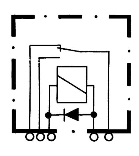
Figure 3: Relay Circuit Diagram. This schematic shows the internal coil, contacts (normally closed and normally open), and the integrated suppression diode across the coil, indicating the directional contact functionality.
5. Návod k obsluze
The HELLA 4RD 933 332-091 relay operates automatically based on the presence or absence of the 24V coil voltage. It functions as a directional contact relay with a normally closed (NC) contact type.
- Stav bez napětí: Když není zvtage is applied to the coil (pins 85 and 86), the common terminal (pin 30) is connected to the Normally Closed (NC) terminal (pin 87a).
- Stav pod napětím: When 24V is applied across the coil (pins 85 and 86), the magnetic field generated pulls the armature, causing the common terminal (pin 30) to switch its connection from the NC terminal (pin 87a) to the Normally Open (NO) terminal (pin 87).
- Suppression Diode: The integrated suppression diode protects the control circuit from voltage spikes that occur when the relay coil is de-energized. This extends the lifespan of other electronic components in the system.
6. Údržba
The HELLA 4RD 933 332-091 relay is designed for long-term reliability and typically requires minimal maintenance. However, periodic inspection can help ensure optimal performance.
- Vizuální kontrola: Periodically inspect the relay and its connections for any signs of physical damage, corrosion, or loose wiring.
- Čištění: If necessary, gently clean the exterior of the relay with a dry, soft cloth. Do not use harsh chemicals or abrasive materials. Ensure no moisture enters the relay.
- Podmínky prostředí: Ensure the operating environment remains within the specified temperature range (-40°C to 125°C) and is free from excessive dust or moisture.
7. Řešení problémů
Pokud relé nefunguje podle očekávání, zvažte následující kroky pro řešení problémů:
- No Switching Action:
- Check if 24V is correctly applied to the coil terminals (85 and 86).
- Verify that the ground connection (pin 85) is secure.
- Inspect for any broken wires or loose connections.
- Ensure the relay is receiving sufficient current.
- Incorrect Switching:
- Confirm that the load is connected to the correct contact (87 for Normally Open, 87a for Normally Closed).
- Review the wiring diagram to ensure all connections match the intended circuit design.
- Přehřívání:
- Ensure the current drawn by the load does not exceed the relay's rated current (20A ohmic, 5A inductive/capacitive).
- Zkontrolujte zkraty v obvodu zátěže.
- Diode Failure: While rare, a damaged suppression diode could lead to issues in the control circuit. If other components are failing after relay de-energization, consider this possibility.
If problems persist after performing these checks, it may indicate a faulty relay or a more complex issue within the electrical system. Consult a qualified automotive electrician or technician.
8. Specifikace
| Funkce | Hodnota |
|---|---|
| Číslo modelu | 4RD 933 332-091 |
| Značka | Hella |
| Coil Voltage | 24 voltů |
| Rated Current (Ohmic Load) | 20 Amps |
| Indukční zátěž | 5 Amps |
| Kapacitní zatížení | 5 Amps |
| Typ konektoru | 5kolíkový konektor |
| Typ kontaktu | Normally Closed (Directional Contact) |
| Provozní režim | Automatický |
| Typ montáže | Držák do auta |
| Teplotní rozsah | -40 °C až 125 °C |
| Rozměry produktu | 3.8 x 3.8 x 7.5 cm |
| Hmotnost položky | 0.03 kilogramu (30 g) |
| Wattage | 120 wattů |
| Specifikace splněna | ISO |
9. Záruka a podpora
For specific warranty information regarding the HELLA 4RD 933 332-091 Main Current Relay, please refer to the documentation provided at the time of purchase or contact your authorized Hella dealer or the point of sale. Warranty terms and conditions may vary by region and retailer.
For technical support, product inquiries, or assistance with troubleshooting beyond the scope of this manual, please visit the official Hella website or contact Hella customer service directly. Ensure you have your product model number (4RD 933 332-091) available when seeking support.